


Sunday, 28 April 2013
FYP 2 Week 14
This week is the presentation day. My assessors were Dr. Haji Zainudin Kornain and Mdm. Izanoordina Bte. Ahmad. I was calm at first but getting more nervous because the assessors were arriving late. I think I did good in the presentation even though I can't answer a few questions from Dr. Haji Zainudin. I managed to speak in English even though the assessors were talking in Bahasa Malaysia. Although I didn't get the top 20 FYP, I still feel relief because the long awaited day had come and passed and I did my best and I accept whatever outcome that I deserve. For now, I have to actually finish the report for the FYP. Alhamdulillah, a weight has been lifted off my shoulder.
Friday, 19 April 2013
FYP 2 Week 13
This week, I still trying to learn how to do Fritzing but I still don't have enough time to absorb it all. In the end I accepted that my circuit doesn't work on PCB board and I have to present my project on breadboard. At least my project does work. Moving on, this week I managed to print out the poster for my presentation day next week.


Sunday, 14 April 2013
FYP 2 Week 12
This week I still continue my etching work. Since I lack experience in etching, it's difficult for me to do it. I have to do my etching twice to make sure the PCB board has my circuit layout from Fritzing clearly. My mistake was I didn't choose the thick wiring for the layout on Fritzing. I only chose the standard wiring, so when I tried to soak the PCB board with acid, the wiring line became too thin and vanished. So I have to redo the etching process again. This time I managed to etch properly.


In the end the circuit constructed on PCB doesn't function because I made some mistakes on the Fritzing layout. I had to present my project on breadboard because I don't have enough time to do the layout on Fritzing again (I still lack the understanding to do the Fritzing). But I still feel relief because my circuit still works as I expected to.
Saturday, 6 April 2013
FYP 2 Week 11
Since I managed to make the circuit work on breadboard, I attempted to construct the circuit on the PCB board using the etching method. First I used the easy-to-use etching software, Fritzing. It is easy to understand for beginners who have never done etching and it is also a free software.
After attempting to do the schematic but still failed to do the wiring, my friend helped me to do this. Here is the result:

After attempting to do the schematic but still failed to do the wiring, my friend helped me to do this. Here is the result:

Sunday, 31 March 2013
FYP 2 Week 10
This week I still test the circuit on breadboard to achieve a much better results. For my project, it has 3 states. The first state is when the fan is not moving if the temperature sensor sense the temperature is below or equal 24°C. The second state is when the temperature is above 24°C, the fan then will move at the normal speed. The third state is when the temperature is above 37°C. If this occurred, the fan will move at its maximum speed.
Here is the results from the serial monitor that you can see from the Arduino 1.0.3 software:


Here is the results from the serial monitor that you can see from the Arduino 1.0.3 software:

Fan started with the normal speed when it doesn't reach the certain temperature.

When the temperature sensor detected the temperature has risen to a certain degree, the fan will increase its speed to maximum.

If the temperature dropped from that certain degree, then the fan will return to its normal speed.
Below is videos of the results of this project on breadboard:
This is video for the first state to the second state (fan turn off -> fan turn on at normal speed)
And this is video for the second state to the third state (fan turn on at normal speed -> fan at maximum speed)
Sunday, 24 March 2013
FYP 2 Week 9
Alhamdulillah, now I finally found the code that works for my circuit. It works beautifully as I have expected. Here is the code:
#include <LiquidCrystal.h>
int pin = 0; // analog pin
int tempc = 0,tempf=0; // temperature variables
int samples[8]; // variables to make a better precision
int maxi = -100,mini = 100; // to start max/min temperature
int i;
int TIP122pin = 9;
int fanspeed = 0;
int fanStemp = 0;
LiquidCrystal lcd(12, 11, 5, 4, 3, 2); // Customize for your connections.
void setup()
{
Serial.begin(9600); // start serial communication
lcd.begin(16,2); // set up the LCD's number of columns and rows
pinMode(TIP122pin, OUTPUT); // Set pin for output to control TIP122 Base pin
analogWrite(TIP122pin, 255); // control the fan speed by changing values from 0 to 255
delay(200);
}
void loop()
{
tempc = 0;
for(i = 0;i<=7;i++){ // gets 8 samples of temperature
samples[i] = ( 5.0 * analogRead(pin) * 100.0 ) / 1024.0;
tempc = tempc + samples[i];
delay(1000);
}
tempc = tempc/8; // better precision
tempf = (tempc * 9)/ 5 + 32; // converts to fahrenheit
if(tempc > maxi) {maxi = tempc;} // set max temperature
if(tempc < mini) {mini = tempc;} // set min temperature
if ( tempc > 24 && tempc < 37 ) {
fanStemp = tempc + 50;
fanspeed = fanStemp + 100;
analogWrite(9,fanspeed);
Serial.print("Fan started at temp+50+100 speed\n");
Serial.print(fanspeed,DEC);
Serial.print("\n");
delay(100);
}
else if ( tempc <= 24 ) {
fanspeed = 0;
analogWrite(9,fanspeed);
Serial.print("Fan off\n");
delay(100);
}
else{
analogWrite(9,255);
Serial.print("Fan started at full speed\n");
delay(100);
}
Serial.print(tempc,DEC); // serial print for debugging all serial.print commands
Serial.print(" Celsius, ");
Serial.print(tempf,DEC);
Serial.print(" fahrenheit -> ");
Serial.print(maxi,DEC);
Serial.print(" Max, ");
Serial.print(mini,DEC);
Serial.println(" Min");
lcd.setCursor(0, 0); // set the cursor to (0,0)
lcd.print(tempc,DEC); // print temp in C and F on the first row of the lcd
lcd.print(" C, ");
lcd.print(tempf,DEC);
lcd.print(" F");
lcd.setCursor(0, 1); // set the cursor to (16,1)
lcd.print(maxi,DEC); // Print max temp and min temp on the second row of lcd
lcd.print(" Max, ");
lcd.print(mini,DEC);
lcd.println(" Min.");
delay(1000); // delay before loop
}
These are the pictures of the constructed circuit on the breadboard:


These are the pictures of the constructed circuit on the breadboard:

The circuit before being plugged with power supply.

The circuit with the power supply, you can see the fan is moving and the LCD display is showing the temperature.
Sunday, 17 March 2013
FYP 2 Week 8
I still cannot come up with the code that works for my project. I try to combine the circuits and the coding but the results always not as what I expected. Because of this, I done some researching of the limitation of this project.
This project, if modified to be a cooling system for human can only work effectively in a small room. This is because the temperature in one room could change easily and the heat sensor could not pick up the sudden change of temperature thus making the fan speed remain the same. The temperature change and the area of the room is the factors here in making the automatic temperature controlled fan speed working effectively. It is also work best for cooling the electrical equipment or machines since it has a more efficient power consumption compared to air conditioner.

This project, if modified to be a cooling system for human can only work effectively in a small room. This is because the temperature in one room could change easily and the heat sensor could not pick up the sudden change of temperature thus making the fan speed remain the same. The temperature change and the area of the room is the factors here in making the automatic temperature controlled fan speed working effectively. It is also work best for cooling the electrical equipment or machines since it has a more efficient power consumption compared to air conditioner.
Saturday, 9 March 2013
FYP 2 Week 7
I still struggling to find functional code that works for my project. In the meantime, I was studying the PWM function with Arduino again.
Pulse Width Modulation, or PWM, is a technique for getting analog results with digital means. Digital control is used to create a square wave, a signal switched between on and off. This on-off pattern can simulate voltages in between full on (5 Volts) and off (0 Volts) by changing the portion of the time the signal spends on versus the time that the signal spends off. The duration of "on time" is called the pulse width. To get varying analog values, you change, or modulate, that pulse width. If you repeat this on-off pattern fast enough with an LED for example, the result is as if the signal is a steady voltage between 0 and 5v controlling the brightness of the LED.
In the graphic below, the green lines represent a regular time period. This duration or period is the inverse of the PWM frequency. In other words, with Arduino's PWM frequency at about 500Hz, the green lines would measure 2 milliseconds each. A call to analogWrite() is on a scale of 0 - 255, such that analogWrite(255) requests a 100% duty cycle (always on), and analogWrite(127) is a 50% duty cycle (on half the time) for example.
I also learned how to combine together the code for temperature sensor and the code for PWM. For example:
Code for temperature sensor:
#include <LiquidCrystal.h>
float tempC;
float tempF;
float voltage;
int reading;
int tempPin=0; //analog channel
int interval = 50; //in ms (how often screen reprints
// initialize the library with the numbers of the interface pins
LiquidCrystal lcd(7, 8, 9, 10, 11, 12);
void setup() {
// set up the LCD’s number of rows and columns:
lcd.begin(20,4);
// Print a message to the LCD.
lcd.setCursor(0,1);
lcd.print("Cabinet Temperature:");
}
void loop() {
//TMP36 voltage at the output varies linearly with ambient temperature.
//As a result,it can be used as a thermometer according to the equation:
// ᵒC = (Vout(V) - .5)*100
//To find Vout in V, we use the following equation for a 5V input
// Vout(V) = AnalogReading*(5/1024)
reading = analogRead(tempPin); //read the value from the sensor
voltage = reading*(5.0/1024); //convert reading to voltage (in V), for 5V input
tempC = (voltage-0.5)*100; //convert voltage to temperature
tempF = ((tempC*9/5)+32); //convert C temperature to F
// (note: line 1 is the second row, since counting begins with 0):
lcd.setCursor(0, 2);// set the cursor to column 0, line 1
lcd.print(tempF); //Print Fahrenheit temperature to LCD
lcd.print((char)223); // degree symbol
lcd.print("F ");
lcd.setCursor(0,3); //print set temp to lcd
lcd.print("Set Temp: 80 ");
lcd.print((char)223);
lcd.print("F");
}
Code for PWM fan:
// Define which pin to be used to communicate with Base pin of TIP120 transistor
int TIP120pin = 3; //for this project, I pick Arduino's PMW pin 3
void setup()
{
pinMode(TIP120pin, OUTPUT); // Set pin for output to control TIP120 Base pin
analogWrite(TIP120pin, 255); // By changing values from 0 to 255 you can control motor speed
}
void loop()
{
}
Code for combined circuit:
#include <LiquidCrystal.h>
float tempC;
float tempF;
float voltage;
int reading;
const int tempPin = 0; //analog channel
const int TIP120pin = 3; //for this project, I pick Arduino's PMW pin 3
const int interval = 50; //in ms (how often screen reprints
const int setPointF = 80;
// initialize the library with the numbers of the interface pins
LiquidCrystal lcd(7, 8, 9, 10, 11, 12);
void setup() {
// set up the LCD’s number of rows and columns:
lcd.begin(20,4);
// Print a message to the LCD.
lcd.setCursor(0,1);
lcd.print("Cabinet Temperature:");
pinMode(TIP120pin, OUTPUT); // Set pin for output to control TIP120 Base pin
}
void loop() {
//TMP36 voltage at the output varies linearly with ambient temperature.
//As a result,it can be used as a thermometer according to the equation:
// ᵒC = (Vout(V) - .5)*100
//To find Vout in V, we use the following equation for a 5V input
// Vout(V) = AnalogReading*(5/1024)
reading = analogRead(tempPin); //read the value from the sensor
voltage = reading*(5.0/1024); //convert reading to voltage (in V), for 5V input
tempC = (voltage-0.5)*100; //convert voltage to temperature
tempF = ((tempC*9/5)+32); //convert C temperature to F
// (note: line 1 is the second row, since counting begins with 0):
lcd.setCursor(0, 2);// set the cursor to column 0, line 1
lcd.print(tempF); //Print Fahrenheit temperature to LCD
lcd.print((char)223); // degree symbol
lcd.print("F ");
lcd.setCursor(0,3); //print set temp to lcd
lcd.print("Set Temp: 80 ");
lcd.print((char)223);
lcd.print("F");
// If the temperature is highher than the set point, run the fans.
// Fans reach full speed then temperature is more than 10°F above setpoint.
analogWrite(TIP120pin, constrain( (tempF - setPointF) * 25, 0, 255));
}
With this examples I will try to come up with new code that can work for my project.
Sunday, 3 March 2013
FYP 2 Week 6
This week I was attempting to combine the codes of temperature sensor and PWM so that the fan will move according to temperature. Unfortunately, I can't find the code that is functional for my project. Here is the example of the code I was using:
#include <LiquidCrystal.h>
LiquidCrystal lcd(12, 11, 5, 4, 3, 2);
const int inPin = 0;
int pwmPin = 9; //digital pin 9
int pwmVal = 10;
void setup()
{
lcd.begin(16, 2);
pinMode(pwmPin, OUTPUT); // sets the pin as output
Serial.begin(9600);
}
void loop()
{
int value = analogRead(inPin);
lcd.setCursor(0, 1);
float milivolts = (value/1024.0)*5000;
float celsius = milivolts/10;
lcd.clear();
lcd.setCursor(0, 0);
lcd.print(celsius);
lcd.print("Celsius");
lcd.setCursor(0, 1);
lcd.print((celsius*9)/5 + 32);
lcd.print("Fahrenheit");
delay(10000);
if (pwmVal != 255) {
analogWrite(pwmPin, pwmVal);
//pwmVal += 10;
Serial.print(pwmVal); // Print red value
Serial.print("\n"); // Print a tab
} else {
Serial.print('at max high'); // Print red value
Serial.print("\n"); // Print a tab
}
delay(1000);
}
When I used this code, only the temperature sensor part work, the fan doesn't move. I still need to understand how to code in Arduino better to make sure my project functions as I desired.
Sunday, 24 February 2013
FYP 2 Week 5
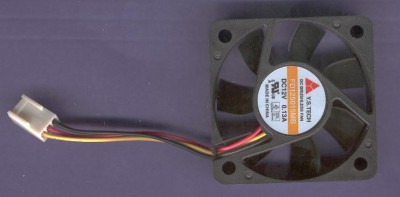
For this week, I was researching what fan should I use for my project. I plan to use DC Fan that is small and portable so that it won't be cumbersome to present on the presentation day. DC fan also easier to be programmed with Arduino compared to AC fan. I decided to use 12V DC Fan. I will be using 9V battery as the power supply and the transistor I use will amplify the power and can make the fan move even the power supply is not 12V.
Saturday, 16 February 2013
Mid semester break
Although it is semester break, I still attempting to test the pulse-width modulation (PWM) function of Arduino. This part is needed to move the fan with a variable speed in my project. After I search the internet, I found the simple code to test PWM with a DC motor. The DC motor speed can be manipulated with the variable resistor. This is the code:
int motor = 9;
int potenciometer = 5;
void setup(){
pinMode(9,OUTPUT);
pinMode(5,INPUT);
Serial.begin(9600);
}
void loop(){
int value = analogRead(potenciometer);
//read input value: range between (0,1023)
int motor_speed = value/4;
//PWM can only ouput 255 different values
analogWrite(motor,motor_speed);
Serial.println(motor_speed);//for testing purposes
}

This is the connection I use to construct on breadboard.
Fortunately, the code works when I tested on breadboard and the results were true as what was expected.

 In this picture, the motor move after I tune the variable resistor. If I tune it all the way, the motor will move to its maximum speed.
For this testing, I used the components DC motor 3V, Variable Resistor 10kΩ, Transistor TIP120, Diode 1N4001, resistor 330Ω and the Arduino microcontroller.
int motor = 9;
int potenciometer = 5;
void setup(){
pinMode(9,OUTPUT);
pinMode(5,INPUT);
Serial.begin(9600);
}
void loop(){
int value = analogRead(potenciometer);
//read input value: range between (0,1023)
int motor_speed = value/4;
//PWM can only ouput 255 different values
analogWrite(motor,motor_speed);
Serial.println(motor_speed);//for testing purposes
}
This is the connection I use to construct on breadboard.
Fortunately, the code works when I tested on breadboard and the results were true as what was expected.

This is before I tune the variable resistor. As you can see, the motor doesn't move.

For this testing, I used the components DC motor 3V, Variable Resistor 10kΩ, Transistor TIP120, Diode 1N4001, resistor 330Ω and the Arduino microcontroller.
Sunday, 10 February 2013
FYP 2 Week 4
Now that I learned about the temperature sensor LM 35, it's time to test it on breadboard. Since I use Arduino microcontroller, I learn how to use LM 35 with Arduino from the internet so that I can understand how does it function. To test it, we also need LCD display to show the temperature values. Below is the connection of Arduino and temperature sensor and the code I used to test the temperature sensor


This is on my own breadboard. It seems the temperature sensor functions as supposed to be.
Saturday, 2 February 2013
FYP 2 Week 3
LM 35 Temperature Sensor

The LM35 is an integrated circuit sensor that can be used to measure temperature with an electrical output proportional to the temperature (in oC)

The LM35 is an integrated circuit sensor that can be used to measure temperature with an electrical output proportional to the temperature (in oC)
- Why Use LM35s To Measure Temperature?
- You can measure temperature more accurately than a using a thermistor.
- The sensor circuitry is sealed and not subject to oxidation, etc.
- The LM35 generates a higher output voltage than thermocouples and may not require that the output voltage be amplified.
Below is the typical performance characteristics of LM35 Temperature Sensor:

So based on the performance characteristic of this temperature sensor, I am confident to choose it since it has good sensitivity and it is also very affordable.
Sunday, 27 January 2013
FYP 2 Week 2
This week I was testing how to use LCD with the Arduino microcontroller. I just learn it from the Arduino website. I'm using the standard 16x2 LCD display. It's easy to display anything you want on the LCD display with Arduino. You just have to understand how to put what you want to display on LCD into your Arduino source code.
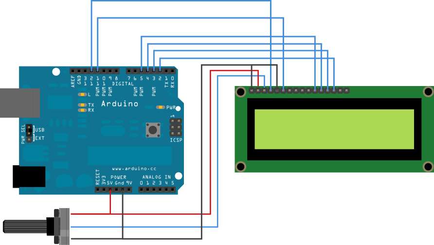
This is the connection of Arduino to LCD
The standard coding for LCD is like this:
/*
LiquidCrystal Library - Hello World
Demonstrates the use a 16x2 LCD display. The LiquidCrystal
library works with all LCD displays that are compatible with the
Hitachi HD44780 driver. There are many of them out there, and you
can usually tell them by the 16-pin interface.
This sketch prints "Hello World!" to the LCD
and shows the time.
The circuit:
* LCD RS pin to digital pin 12
* LCD Enable pin to digital pin 11
* LCD D4 pin to digital pin 5
* LCD D5 pin to digital pin 4
* LCD D6 pin to digital pin 3
* LCD D7 pin to digital pin 2
* LCD R/W pin to ground
* 10K resistor:
* ends to +5V and ground
* wiper to LCD VO pin (pin 3)
Library originally added 18 Apr 2008
by David A. Mellis
library modified 5 Jul 2009
by Limor Fried (http://www.ladyada.net)
example added 9 Jul 2009
by Tom Igoe
modified 22 Nov 2010
by Tom Igoe
This example code is in the public domain.
http://www.arduino.cc/en/Tutorial/LiquidCrystal
*/
// include the library code:
#include <LiquidCrystal.h>
// initialize the library with the numbers of the interface pins
LiquidCrystal lcd(12, 11, 5, 4, 3, 2);
void setup() {
// set up the LCD's number of columns and rows:
lcd.begin(16, 2);
// Print a message to the LCD.
lcd.print("hello, world!");
}
void loop() {
// set the cursor to column 0, line 1
// (note: line 1 is the second row, since counting begins with 0):
lcd.setCursor(0, 1);
// print the number of seconds since reset:
lcd.print(millis()/1000);
}
Tuesday, 15 January 2013
FYP 2 Week 1
This is the first week of FYP 2. So far I have only bought the components for my project but I haven't started the project. I also met my supervisor, Sir Halim to ask him about how to proceed with FYP in this semester.
For my project, I plan on using temperature sensor, 16x2 LCD display to display the temperature, DC fan that will spin according to the temperature and the Arduino microcontroller.
For my project, I plan on using temperature sensor, 16x2 LCD display to display the temperature, DC fan that will spin according to the temperature and the Arduino microcontroller.
Subscribe to:
Posts (Atom)